Equaliser design using eqfil

Dear Csounders!

How to properly implement an i.e. 5 band equaliser using eqfil opcode?

This is my code below and no matter which gains (kgain) I put here I don’t hear any difference.

<CsInstruments>
; Initialize the global variables. 
ksmps = 32
nchnls = 2
0dbfs = 1

instr 1
    // EQ initialization and parameters
    kcf[] fillarray 50, 200, 800, 3200, 12000
    kbw[] fillarray 25, 100, 400, 1600, 6000
    kgain[] fillarray 1, 0.1, 0.01, 0.3, 0.05  
    aEqOut[] init 5
    
    // sound synthesis
    aOut vco2 p5, p4
    
    // EQ filtering
    aEqOut[0] eqfil aOut, kcf[0], kbw[0], kgain[0], 1
    aEqOut[1] eqfil aOut, kcf[1], kbw[1], kgain[1], 1
    aEqOut[2] eqfil aOut, kcf[2], kbw[2], kgain[2], 1
    aEqOut[3] eqfil aOut, kcf[3], kbw[3], kgain[3], 1
    aEqOut[4] eqfil aOut, kcf[4], kbw[4], kgain[4], 1
    
    aRes = 0  // resulting audio vector
    kIndx = 0
    while (kIndx < lenarray(aEqOut)) do
        aRes += aEqOut[kIndx]
        kIndx += 1
    od    

    // write result to output buffer
    outs aRes, aRes
endin
</CsInstruments>

Any thoughts?

Simply a few minor errors from what I can tell. Running the while loop at k rate runs thru the arrays so quickly it creates havoc so I replaced with a metro so you could hear each band switch more distinctly. And kres += doesn’t work, should be kres = , no need to init.

Replaced a few gain values, just because I felt like playing around.

<CsoundSynthesizer>
<CsOptions>
-odac
</CsOptions>

<CsInstruments>
; Initialize the global variables. 
ksmps = 32
nchnls = 2
0dbfs = 1

instr 1
    // EQ initialization and parameters
    kcf[] fillarray 50, 200, 800, 3200, 12000
    kbw[] fillarray 25, 100, 400, 1600, 6000
    kgain[] fillarray 1, 3, 0.01, 0.1, 0.05  
    aEqOut[] init 5
    
    // sound synthesis
    aOut vco2 p5, p4
    
    // EQ filtering
    aEqOut[0] eqfil aOut, kcf[0], kbw[0], kgain[0], 1
    aEqOut[1] eqfil aOut, kcf[1], kbw[1], kgain[1], 1
    aEqOut[2] eqfil aOut, kcf[2], kbw[2], kgain[2], 1
    aEqOut[3] eqfil aOut, kcf[3], kbw[3], kgain[3], 1
    aEqOut[4] eqfil aOut, kcf[4], kbw[4], kgain[4], 1
    
;    aRes  init 0 // resulting audio vector
    kIndx init -1
    ktrig metro 1
    if  ktrig == 1 then
        kIndx += 1
    endif   
    aRes = aEqOut[kIndx]
       

    // write result to output buffer
    outs aRes, aRes
endin

instr 2
    aOut vco2 p5, p4
    outs aOut, aOut
endin

instr 3
    // EQ initialization and parameters
    kcf[] fillarray 50, 200, 800, 3200, 12000
    kbw[] fillarray 25, 100, 400, 1600, 6000
    kgain[] fillarray -.3, 6, 0.01, 0.03, 0.05  
    aEqOut[] init 5
    
    // sound synthesis
    aOut vco2 p5/5, p4
    
    // EQ filtering
    aEqOut[0] eqfil aOut, kcf[0], kbw[0], kgain[0], 1
    aEqOut[1] eqfil aOut, kcf[1], kbw[1], kgain[1], 1
    aEqOut[2] eqfil aOut, kcf[2], kbw[2], kgain[2], 1
    aEqOut[3] eqfil aOut, kcf[3], kbw[3], kgain[3], 1
    aEqOut[4] eqfil aOut, kcf[4], kbw[4], kgain[4], 1
    
;    aRes  init 0 // resulting audio vector
    aRes = aEqOut[0]+aEqOut[1]+aEqOut[2]+aEqOut[3]+aEqOut[4]          
       

    // write result to output buffer
    outs aRes, aRes
endin


</CsInstruments>
<CsScore>
i2  0 4 220 .45
i3  5 4 220 .45
i1 11 5 220 .45
</CsScore>
</CsoundSynthesizer>

Well, apologies, guess my head wasn’t in the game when I first tried this. The k rate loop works fine. I’m not familiar with the eqfil opcode but noticed the gain values aren’t as subtle as when using a normalized gain ratio. So the eq you designed seems to work fine but with the saw osc stronger gain values seem more audible. The saw has alot more harmonics, if you try this example but with an oscil you can really hear the eq is working.

Nice design btw.

<CsoundSynthesizer>
<CsOptions>
-odac
</CsOptions>

<CsInstruments>
; Initialize the global variables. 
ksmps = 32
nchnls = 2
0dbfs = 1

instr 1
    // EQ initialization and parameters
    kcf[] fillarray 50, 200, 800, 3200, 12000
    kbw[] fillarray 25, 100, 400, 1600, 6000
    kgain[] fillarray 1, 1, 1, 4, 0.05  
    aEqOut[] init 5
    
    // sound synthesis
    aOut vco2 p5/5, p4
    
    // EQ filtering
    aEqOut[0] eqfil aOut, kcf[0], kbw[0], kgain[0], 1
    aEqOut[1] eqfil aOut, kcf[1], kbw[1], kgain[1], 1
    aEqOut[2] eqfil aOut, kcf[2], kbw[2], kgain[2], 1
    aEqOut[3] eqfil aOut, kcf[3], kbw[3], kgain[3], 1
    aEqOut[4] eqfil aOut, kcf[4], kbw[4], kgain[4], 1        
    aRes  = 0 // resulting audio vector
    kIndx = 0
    while (kIndx < lenarray(aEqOut)) do
        aRes += aEqOut[kIndx]
        kIndx += 1
    od    
 
    // test
    kline = linseg(1, p3/2, -3, p3/2, -3)
    kgain[1] = kline
    kgain[2] = kline
    kline2 = linseg(0.3, p3/2, 6, p3/2, 6)
    kgain[3] = kline2
    
    // write result to output buffer
    outs aRes, aRes
endin

instr 2
aOut vco2 p5, p4
    outs aOut, aOut
endin

</CsInstruments>
<CsScore>
i2 0 4 220 .5
i1 5 4 220 .5
</CsScore>
</CsoundSynthesizer>

Hi @ST_Music

Thanks for your feedback! I somehow missed the notification when you replied :sweat_smile:

In meantime, I decided to use butterbp opcode instead eqfil. I’m not sure what is wrong with eqfil but when compared with butterbp it seems that it’s not working correctly (I’m using Csound version 6.18).

Check out this code below where those two opcodes are directly compared:

<CsOptions>
-odac
</CsOptions>

<CsInstruments>
; Initialize the global variables. 
ksmps = 32
nchnls = 2
0dbfs = 1


// EQ parameters
gicf[] fillarray 50, 200, 800, 3200, 12000
gibw[] fillarray 25, 100, 400, 1600, 6000
gigain[] fillarray 1, 1, 1, 1, 1  

instr ButterBP   
    // sound synthesis
    aOut vco2 p5, p4
    
    // apply butterbp in wanted band
    aRes butterbp  aOut, gicf[p6], gibw[p6]
    aRes *= gigain[p6]    ; gain in this case needs to be done separatly
 
    // write result to output buffer
    outs aRes, aRes
endin


instr EqFil  
    // sound synthesis
    aOut vco2 p5, p4    
  
    // apply eqfil in wanted band
    aRes eqfil aOut, gicf[p6], gibw[p6], gigain[p6], 1
    
    // write result to output buffer
    outs aRes, aRes
endin

</CsInstruments>
<CsScore>
; test 50HZ band with both filters
i "EqFil" 0 2 220 .5 0
i "ButterBP" 3 2 220 .5 0

; test 800HZ band with both filters
i "EqFil" 6 2 220 .5 2 
i "ButterBP" 9 2 220 .5 2 

; test 12000HZ band with both filters
i "EqFil" 12 2 220 .5 4
i "ButterBP" 15 2 220 .5 4
</CsScore>
</CsoundSynthesizer>

Am I missing something here?

Yes, I think you are missing something. :smile:

A parametric eq should pass the original signal thru, boosting or cutting only the desired frequencies.

It appears you are using eqfil incorrectly. To boost a freq the gain value must be >1. To cut a freq the gain value must be <1. You have all the gain values set to 1 which is essentially directing the eqfil to do nothing.

From the manual (eqfil) :
“The amplitude response for this filter will be flat (=1) for kgain=1. With kgain bigger than 1, there will be a peak at the centre frequency.”

“flat” means unchanged, no boost/cut. The selected frequency will not be altered.

Gain values of 1 in the eqfil means you are neither boosting nor cutting any freq, it is doing nothing except passing the original audio signal thru, which is why the signal sounds unaltered. Therefore eqfil is acting correctly - it is following your instructions.

The butbp does not pass thru the unaffected frequencies as an eq should. It cannot lower (cut) a selected frequency range, nor boost it while leaving other frequencies unaltered. It is filtering out (removing) frequencies outside of the bandwidth range which is why there is so much signal loss with butlp and the audio is so much quieter.

A proper eq should pass unaffected frequencies thru at their original amplitude and only boost/cut selected frequencies. butbp cannot achieve this properly. It can only filter out unwanted frequencies outside of the bandwidth surrounding the cutoff frequency and try to keep or boost most frequencies that fall inside the bandwidth.

It only sounds like butlp is doing more because it is negatively altering the original signal whereas eqfil is doing nothing but passing thru the original signal with no boost or cut, as it should with gain=1.

You could potentially add butbp boosted freq to the original but that seems rather inefficient, and a parametric eq should allow cutting/lowering/notching out unwanted frequencies. butbp will not do that. eqfil, or something like the rbjeq opcode, will do this much more efficiently if used correctly

I will try to post a better example later today.

Here is an example. The egfil array values have been altered to boost the harmonics of the saw wave to demonstrate. Notice index 0 of gigain is set to 1 - no boost or cut. So first you will hear only the original audio. Then you will hear each harmonic emphasized but you will also hear how the rest of the frequencies pass thru unaltered as they should.

<CsoundSynthesizer>
<CsOptions>
-odac
; -o eq.wav
</CsOptions>

<CsInstruments>
; Initialize the global variables. 
ksmps = 32
nchnls = 2
0dbfs  = 1

// EQ parameters, frequencies tuned to harmonics
gicf[] fillarray 220, 220, 440, 659.26, 880, 1108.7
gibw[] fillarray 20, 20, 20, 20, 20, 20
gigain[] fillarray 1, 4.5, 7, 10, 12, 16

instr EqFil  
    // sound synthesis
    aamp linseg 0, .1, 1, p3 - .2, 1, .1, 0
    
    aOut vco2 p5, p4
  
    // apply eqfil in wanted band
    aRes eqfil aOut * aamp, gicf[p6], gibw[p6], gigain[p6], 1
    
    // write result to output buffer
    outs aRes, aRes

endin

</CsInstruments>
<CsScore>
; no boost/cut 
i "EqFil"  0  2 220 .3 0
; test 200 HZ (fundamental)
i .        +  .  .  .  1
; test 400 HZ (octave)
i .        +  .  .  .  2
; test 659.26 HZ (5th)
i .        +  .  .  .  3
; test 880 HZ (octave)
i .        +  .  .  .  4
; test 1108.7 (major 3rd)
i .        +  .  .  .  5

</CsScore>
</CsoundSynthesizer>

Your original design was fine but you were not using adequate gain values. And instead of a loop it is much simpler to just sum the array indexes.

    aEqOut[0] eqfil aOut, kcf[0], kbw[0], kgain[0], 0
    aEqOut[1] eqfil aOut, kcf[1], kbw[1], kgain[1], 0
    aEqOut[2] eqfil aOut, kcf[2], kbw[2], kgain[2], 0
    aEqOut[3] eqfil aOut, kcf[3], kbw[3], kgain[3], 0
    aEqOut[4] eqfil aOut, kcf[4], kbw[4], kgain[4], 0          
    aRes  = sumarray(aEqOut) // resulting audio vector

Hope that helps a bit. Best,
Scott

1 Like

Hi Scott!

Thank you very much on your clear explanation and a nice example :beers:

Now I understand the difference between two opcodes. I was using eqfil as a “standard” bandpass filter but actually butterbp is what I needed.

If anyone else lands here with a similar problem here is a simple equaliser example with a GUI (made in Cabbage but can be easily transferred to anywhere else) that can be used as a starting point:

<Cabbage>
form caption("5-band Equaliser") size(400, 420), guiMode("queue"), pluginId("def1")
keyboard bounds(10, 302, 382, 95) channel("keyboard2")

rslider bounds(0, 198, 82, 80) channel("gain_0") range(-60, 10, 0, 1, 0.01) valueTextBox(1) fontColour(0, 0, 0, 255)
rslider bounds(80, 200, 82, 80) channel("gain_1") range(-60, 10, 0, 1, 0.01) valueTextBox(1) fontColour(0, 0, 0, 255)
rslider bounds(160, 200, 82, 80) channel("gain_2") range(-60, 10, 0, 1, 0.01) valueTextBox(1) fontColour(0, 0, 0, 255)
rslider bounds(240, 200, 82, 80) channel("gain_3") range(-60, 10, 0, 1, 0.01) valueTextBox(1) fontColour(0, 0, 0, 255)
rslider bounds(320, 200, 82, 80) channel("gain_4") range(-60, 10, 0, 1, 0.01) valueTextBox(1) fontColour(0, 0, 0, 255)


vslider bounds(-30, 54, 150, 150) channel("level_0") range(0, 80, 20, 1, 0.1) active(0) colour(0, 0, 0, 0)
vslider bounds(50, 54, 150, 150) channel("level_1") range(0, 80, 20, 1, 0.1) active(0) colour(0, 0, 0, 0)
vslider bounds(130, 54, 150, 150) channel("level_2") range(0, 80, 20, 1, 0.1) active(0) colour(0, 0, 0, 0)
vslider bounds(210, 54, 150, 150) channel("level_3") range(0, 80, 20, 1, 0.1) active(0) colour(0, 0, 0, 0)
vslider bounds(290, 54, 150, 150) channel("level_4") range(0, 80, 20, 1, 0.1) active(0) colour(0, 0, 0, 0)

label bounds(30, 280, 24, 16) channel("label_0") text("dB")
label bounds(110, 280, 24, 16) channel("label_1")  text("dB")
label bounds(190, 280, 24, 16) channel("label_2")  text("dB")
label bounds(270, 280, 24, 16) channel("label_3")  text("dB")
label bounds(350, 280, 24, 16) channel("label_4")  text("dB")

label bounds(32, 0, 338, 46) channel("title_label") text("EQ+Monitor")


</Cabbage>
<CsoundSynthesizer>
<CsOptions>
-n -d -+rtmidi=NULL -M0 -m0d --midi-key-cps=4 --midi-velocity-amp=5
</CsOptions>
<CsInstruments>
; Initialize the global variables. 
ksmps = 32
nchnls = 2
0dbfs = 1

;instrument will be triggered by keyboard widget
instr 1

    kgains[] init 5
    kgains[0] = cabbageGetValue:k("gain_0")
    kgains[1] = cabbageGetValue:k("gain_1")
    kgains[2] = cabbageGetValue:k("gain_2")
    kgains[3] = cabbageGetValue:k("gain_3")
    kgains[4] = cabbageGetValue:k("gain_4")
    
   // Define cutoff frequency of a lowpass filter
    klc = 100  // in Hz
    // Define the central frequencies and bandwidths for pass band filters
    kcf[] fillarray 300, 1200, 3500 // in Hz
    kbw[] fillarray 300, 1000, 2500 // in Hz
    // Define cutoff frequency of a highpass filter
    khc = 8000  // in Hz

     // Arrays initialization
    aEqOuts[] init 5
    aBandOuts[] init 5
    kBandLvls[] init 5

    // sound synthesis
    aOut poscil p5, p4
    
    // EQ filtering
    //aEqOuts[0] butterbp  aOut, kcf[0], kbw[0]
    aEqOuts[0] butterlp  aOut, klc 
    aEqOuts[1] butterbp  aOut, kcf[0], kbw[0]
    aEqOuts[2] butterbp  aOut, kcf[1], kbw[1]
    aEqOuts[3] butterbp  aOut, kcf[2], kbw[2]
    aEqOuts[4] butterhp  aOut, khc
    
    // Apply band gains
    aRes = 0  // resulting audio vector
    kIndx = 0
    while (kIndx < lenarray(aEqOuts)) do
        aBandOuts[kIndx] = aEqOuts[kIndx] * ampdb(kgains[kIndx])
        
        aRes += aBandOuts[kIndx]
        kIndx += 1
    od
    
    
    // Calculate RMS for monitor
    kBandLvls[0] rms aBandOuts[0]
    kBandLvls[1] rms aBandOuts[1]
    kBandLvls[2] rms aBandOuts[2]
    kBandLvls[3] rms aBandOuts[3]
    kBandLvls[4] rms aBandOuts[4]
    
    
    // Monitor (GUI) update
    kIndx = 0
    while (kIndx < lenarray(aEqOuts)) do
        Schann sprintfk "level_%d", kIndx
        kMonitorVal = dbamp(kBandLvls[kIndx]) + 70
        cabbageSetValue Schann, kMonitorVal
        
        kIndx += 1
    od    
    
    // envelope generation
    kEnv madsr .1, .2, .6, .4
    
    // write output to output buffer
    outs aRes*kEnv, aRes*kEnv
endin

</CsInstruments>
<CsScore>
f0 z
</CsScore>
</CsoundSynthesizer>

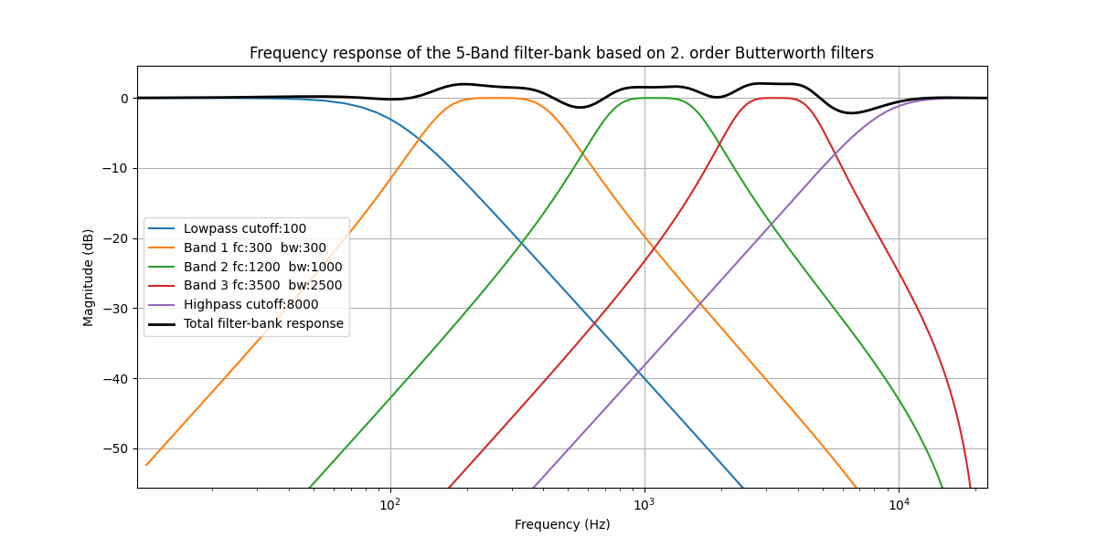
I’m pretty sure that this filterbank is not the best one so if anyone wants to experiment a bit with different ones e.g. with different central frequencies and bandwidths or different number bands, here is a python script that will plot its frequency response:

import numpy as np
import matplotlib.pyplot as plt
from scipy.signal import butter, freqz

# Define cutoff frequency of a lowpass filter
lowcutoff = 100  # in Hz
# Define the central frequencies and bandwidths for pass band filters
central_frequencies = [300, 1200, 3500]  # in Hz
bandwidths = [300, 1000, 2500]  # in Hz
# Define cutoff frequency of a highpass filter
highcutoff = 8000  # in Hz

# Sampling frequency and order of the Butterworth filters
fs = 44100  # Sample rate in Hz
order = 2  # Order of the Butterworth filters
nyquist = 0.5 * fs

# Construct the filter bank
filter_bank = []
# construct lowpass filter
b, a = butter(order, lowcutoff/nyquist, btype='low')
filter_bank.append((b, a))
# construct bandpass filters
for center, bandwidth in zip(central_frequencies, bandwidths):
    lowcut = center - bandwidth / 2
    highcut = center + bandwidth / 2
    low = lowcut / nyquist
    high = highcut / nyquist
    b, a = butter(order, [low, high], btype='band')
    filter_bank.append((b, a))
# construct highpass filter
b, a = butter(order, highcutoff/nyquist, btype='high')
filter_bank.append((b, a))

# Plot the frequency response of each filter
plt.figure(figsize=(12, 6))
for b, a in filter_bank:
    w, h = freqz(b, a, fs=fs)
    plt.plot(w, 20 * np.log10(np.abs(h)))
    
# Calculate and plot the sum of all responses
total_response = np.zeros_like(w)
for b, a in filter_bank:
    w, h = freqz(b, a, fs=fs)
    total_response += np.abs(h)
plt.plot(w, 20 * np.log10(total_response), 'k', linewidth=2)

plt.xlabel('Frequency (Hz)')
plt.ylabel('Magnitude (dB)')
plt.title(f'Frequency response of the 5-Band filter-bank based on {order}. order Butterworth filters')
plt.xscale('log')
plt.legend([f'Lowpass cutoff:{lowcutoff}', 
            f'Band 1 fc:{central_frequencies[0]}  bw:{bandwidths[0]}', 
            f'Band 2 fc:{central_frequencies[1]}  bw:{bandwidths[1]}', 
            f'Band 3 fc:{central_frequencies[2]}  bw:{bandwidths[2]}', 
            f'Highpass cutoff:{highcutoff}',
            'Total filter-bank response'])
plt.grid(True)
plt.show()

Please correct me if I’m wrong here, basically the flatter the frequency response the better but, that being said, more important is that you know what you have; in this case that would be

Hi again, Lovre. :saluting_face:

Perhaps just an initial miscommunication. I thought you wanted to build a standard parametric eq, not a series of bandpass filters.

I must admit I am still unsure of your goal.

Please forgive my following long response, I’m not always skilled at being concise.

Flat response of an audio signal is not necessarily better as an end result, but ideally an eq should have the ability to be in the audio path without colouring the signal noticeably except as desired. So the eq response should be flat if there are no boosts/cuts. From my understanding, the general goal of a parametric eq is to target specific frequency ranges, not necessarily for the purpose of ending with a flat response. But it should usually start with a flat response. The eq should be “transparent”.

With eqfil, pareq, rbjeq opcodes (as examples) you are starting with a flat response and can then alter specific frequencies precisely by boosting or cutting.

What you have created essentially seperates all frequencies and adds these together, leaving extremely large notches (dips) between bands, as large as - 20 or -30dB. So unlike the parametric opcodes, your starting point using multiple butbp filters is not a flat response to begin with. This is probably undesirable for a parametric eq.

While plotting in python may seem like a good idea, it is theoretical. It doesn’t necessarily reflect what an opcode is doing in real-world application. One should generally start by testing an eq’s response by passing white noise thru it since noise contains equal amounts of all frequencies. This should be viewed using a spectrum analyzer.

Passing white noise thru your butbp eq, with no boosts or cuts (all gain values = 0), results in this:

Unlike the plotting in python, the actual response is far from flat, it is undesirably affecting many areas of the spectrum.

However, passing white noise thru an eqfil with no boosts/cuts results in a generally flat response:

It may appear that there are very small boosts/cuts but that is because white noise has small amplitude modulations between individual time samples.

A parametric eq may often be used to target very specific frequencies while remaining transparent (flat) to surrounding frequencies, for example eliminating a ringing overtone from a snare drum, using a narrow bw. When I attempted to cut a 300 Hz freq with your filter using a tight Q (a narrow bw, which creates a notch) it results in the bandpass filter negatively eliminating a very wide band of frequencies since it no longer passes them thru. Note that the 4 other gains were left untouched (value of 0):

So while attempting to target only one freq the butbp design seems to have an effect on a wide spectrum. It is far from being flat when attempting to cut a frequency.

With eqfilt, it was able to cut (notch) the targeted freq (300 Hz) efficiently without affecting the surrounding frequencies - they remained essentially flat:

And with the eqfil, it is also easy to target a wide band of frequencies if desired using a wider bw.

If your goal is to have a low & high shelf eq along with 3 filters for variable bw boost/cut then perhaps perhaps you should look at the pareq or rbjeq opcodes.

I’m certainly no expert and perhaps misinterpreted your goals or tested your design incorrectly, if so I apologize. This is only reflects my limited opinion. But from my understanding of a parametric eq your previous (initial) design is probably much more effective.

As you stated, if I’m misunderstanding something, please feel free to correct me.

1 Like

I decided to test the eqs a bit more.

The first video shows a 3 part test using 3 instr: noise only, noise thru 5 eqfil in series, and then noise thru the butlp filters. The filters used no boost or cut.

The unfiltered noise and cascading eqfil instruments’ output look identical. It seems that eqfil is more transparent so probably better suited for a parametric eq. Based on that I decided to further test it. The opcode is based on Regalia and Mitra design (“Tunable Digital Frequency Response Equalization Filters”, IEEE Trans. on Ac., Sp. and Sig Proc., 35 (1), 1987). You can read that here:

The concluding remarks suggest the filters should be cascaded (in series). This makes sense. If the filters are run in parallel and only one filter is affecting a specific frequency, then the other four parallel filters still pass that freq thru and when subsequently summed are largely negating the boost/cut of the one eqfil that is boosting/notching.

Here’s the code I used for the next test/video:

<CsoundSynthesizer>
<CsOptions>
-o dac
; -o paraeq_test2.wav 
</CsOptions>

<CsInstruments>
; Initialize the global variables. 
sr = 48000
ksmps = 32
nchnls = 2
0dbfs  = 1

instr 1
    // EQ initialization and parameters
    kcf[]   fillarray 50, 200, 800, 3200, 12000
    kbw[]   fillarray 25, 200, 400, 1200, 6000
    kgain[] fillarray 1, 1, 1, 1, 1 ; flat frequency response
    
    // sound synthesis
    aOut noise .9, 0
    
    // EQ filtering
    ktest = linseg(0, 2, 0, 3, -1, 3, -1, 3, 0, 3, 4, 3, 4, 3, 0, 2, 0)
    ktst2 = linseg(0, 2, 0, 3, 4, 3, 4, 3, 0, 3, -1, 3, -1, 3, 0, 2, 0)
    aOut    eqfil aOut, kcf[0], kbw[0], kgain[0]
    aOut    eqfil aOut, kcf[1], kbw[1], kgain[1] + ktest
    aOut    eqfil aOut, kcf[2], kbw[2], kgain[2]
    aOut    eqfil aOut, kcf[3], kbw[3], kgain[3] + ktst2     
    aOut    eqfil aOut, kcf[4], kbw[4], kgain[4]       
    kAttn = .4 ; attenuation
    aOut *= kAttn
            outs  aOut, aOut
endin

</CsInstruments>
<CsScore>
i1  0  22
</CsScore>
</CsoundSynthesizer>

The second video demonstrates boosting 3kHz and then notching 200 Hz followed by the opposite, while leaving other frequencies flat.

One caveat - when cutting frequencies (gain values between 1 and 0) as opposed to boosting, eqfil appears to be more of a notch filter (narrow bandwidth) and bandwidth should be wider than when boosting to affect a similar frequency range.

I’m always trying to learn more about Csound so if anyone sees something I’m missing here it would be good to know.

1 Like

Hi Scott!

Wow :open_mouth: that is a high quality text you wrote! Really nice analysis :clap:

… I thought you wanted to build a standard parametric eq, not a series of bandpass filters.

From the start I wanted to decompose input signal into arbitrary number of frequency bands and then to measure e.g. energies in each band. And then I thought, ok I could make an EQ as wrapper around it so that I can play a bit with those bands. And then I started to look which opcode can I use for that and I landed on eqfil so I tried it but it didn’t work as I thought it should.
Now I see that eqfil is not designed for this kind of application in mind and that I was using it wrong. Actually what I was looking for are standard filter opcodes like Butterworth and so on.

I know that the thread’s title could be a bit confusing for the people who land on this page in the future but your example above shows very nicely how to use eqfil opcode properly and how to make a parametric EQ with it. And if someone wants to experiment a bit with filter banks, the code from my previous post could be used as a starting point.

Unlike the plotting in python, the actual response is far from flat, it is undesirably affecting many areas of the spectrum

Yes, yes I know that my filter bank is not a especially good one. It is just an example how to build a filter bank. But what worries me is that the responses are different around 100Hz (rest of the responses actually match nicely if you look cuts around 500Hz, 2kHz and 7kHz and boosts around them). If I find what causes this mismatch I will post it here.

Once again, thank you Scott very much on your help and clarifications :beers:

1 Like

Hi Lovre. Thank you for the clarification.

I did a little research and see now that there can be several applications for the filterbanks, I was not familiar with that concept. I see some used for analysis, others for sound design.

I did notice Csound has at least one filterbank opcode (mfb, Mel scale filterbank) but it does look quite different than the others I saw on Google.

Of course now I’m somewhat curious :sweat_smile:. If you find some practical applications for this hopefully you can share them here, it’s always interesting to see different ways to mess around with audio signals. :beers: to you as well!